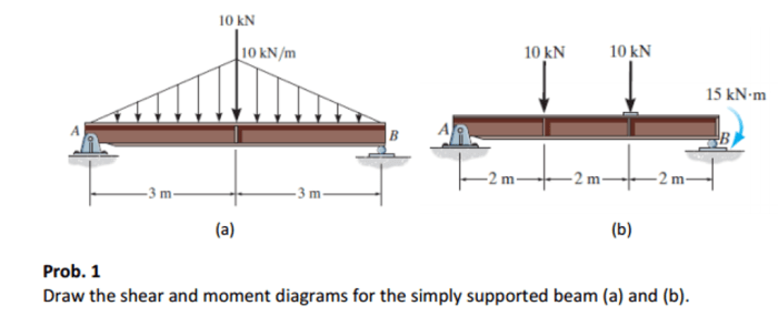
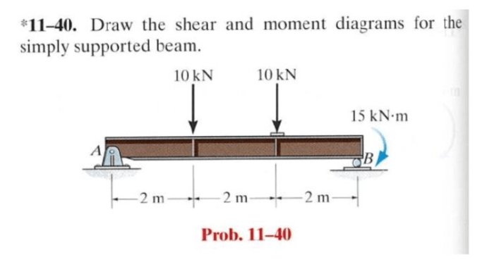
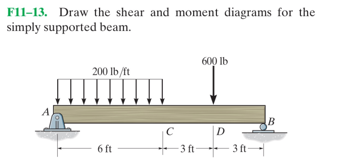
Draw the shear and moment diagrams for the simply-supported beam – Understanding the shear and moment diagrams for simply-supported beams is crucial for structural analysis and design. These diagrams provide valuable insights into the internal forces and stresses within the beam, enabling engineers to assess its structural integrity and optimize its performance.
This comprehensive guide will delve into the concepts of shear force and bending moment, explaining how to calculate these values and construct accurate shear and moment diagrams for simply-supported beams. By following the step-by-step procedures Artikeld in this guide, readers will gain a thorough understanding of this essential aspect of structural mechanics.
Define the Beam and its Support Conditions

A simply-supported beam is a structural element that rests on two supports at its ends, allowing it to rotate freely but preventing any vertical movement. This type of support condition creates specific boundary conditions and reactions at the supports.
Boundary Conditions
- Zero vertical displacement at the supports (v = 0)
- Zero bending moment at the supports (M = 0)
Reactions at the Supports
- Vertical reactions at each support, equal to half of the total applied load
- No horizontal reactions
Determine the Loading Conditions

The loading conditions acting on the beam can include point loads, distributed loads, and moments. These loads can be applied at any point along the beam’s length.
Types of Loads
- Point loads:Concentrated forces applied at specific points
- Distributed loads:Forces distributed over a certain length of the beam
- Moments:External forces that cause rotation
Location and Magnitude
The location and magnitude of each load must be clearly defined to determine their effects on the beam.
Calculate Shear Forces: Draw The Shear And Moment Diagrams For The Simply-supported Beam

Shear force (V) represents the internal force that resists the tendency of the beam to bend or twist. It is calculated by taking the algebraic sum of all vertical forces acting on the beam to the left or right of the point of interest.
Step-by-Step Method
- Cut the beam at the point of interest.
- Sum the vertical forces acting on the left (or right) portion of the beam.
- The shear force at the point of interest is equal to this sum.
Calculate Bending Moments

Bending moment (M) represents the internal force that resists the tendency of the beam to bend. It is calculated by taking the algebraic sum of all moments acting on the beam to the left or right of the point of interest.
Step-by-Step Method
- Cut the beam at the point of interest.
- Sum the moments of all forces acting on the left (or right) portion of the beam about the point of interest.
- The bending moment at the point of interest is equal to this sum.
Draw the Shear and Moment Diagrams
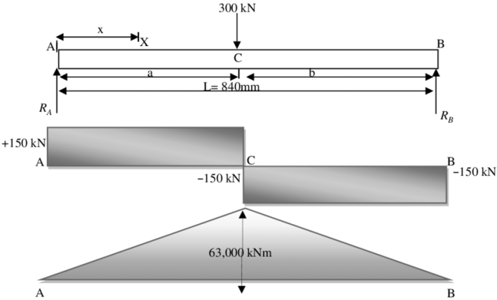
The shear and moment diagrams are graphical representations of the shear forces and bending moments along the beam’s length.
Shear Diagram, Draw the shear and moment diagrams for the simply-supported beam
The shear diagram shows the variation of shear force along the beam. It is constructed by plotting the calculated shear forces at different points along the beam.
Moment Diagram
The moment diagram shows the variation of bending moment along the beam. It is constructed by plotting the calculated bending moments at different points along the beam.
Labeling and Critical Points
The diagrams should be clearly labeled with the values of shear forces and bending moments at critical points, such as supports, points of load application, and points of maximum shear or moment.
FAQs
What is a simply-supported beam?
A simply-supported beam is a structural element that rests on two supports, with no other constraints along its length. The supports allow the beam to rotate freely, but they prevent any vertical displacement or horizontal movement.
What is shear force?
Shear force is the internal force that resists the tendency of a beam to bend or twist. It is caused by transverse loads applied to the beam, such as point loads or distributed loads.
What is bending moment?
Bending moment is the internal force that resists the tendency of a beam to bend. It is caused by moments applied to the beam, such as concentrated moments or distributed moments.